Bilaterals landmarks
Frontotemporale
Abbreviature: ft´ L / ft´ R
Laterality: Bilateral
Type: 2
Standardized definition (Caple y Stephan, 2015): Point of concavity on each side of the forehead above the supraorbital rim, lateral to the elevation of the linea temporalis.
Approximation in the image: Zoom in on the upper half of the face.
Anatomical reference areas: Linea temporalis.
Guidelines for Skeleton·ID frontal view marking:
Place frontotemporale on the lateral concavities on each side of the forehead, lateral to the elevation of the linea temporalis. The vertical auxiliary line should be placed on the interior lateral border of the linea temporalis (toward the rostral region) and the horizontal auxiliary line in the midpoint of the concavity. Follow the same procedure to mark the contralateral point.
 Figure 1. Frontotemporale (left and right) in frontal view. General shot of the image.
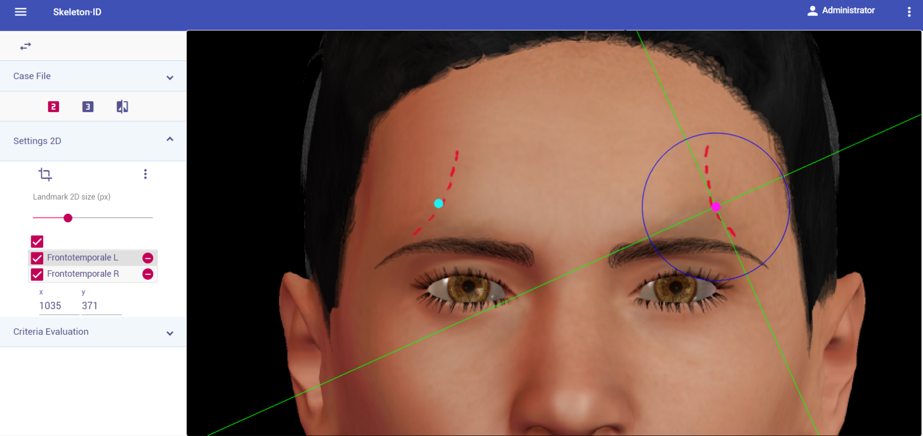 Figure 2. Frontotemporale (left and right) in frontal view. Approximation in the image.
Guidelines for Skeleton·ID lateral view marking:
Place frontotemporale on the concavities lateral to the elevation of the línea temporalis. The vertical auxiliary line should be placed on the interior lateral border of the linea temporalis (toward the rostral region) and the horizontal auxiliary line in the midpoint of the concavity. Note that the contralateral point cannot be estimated.
 Figure 3. Frontotemporale (left) in lateral view. General shot of the image.
 Figure 4. Frontotemporale (left) in lateral view. Approximation in the image.
Guidelines for Skeleton·ID oblique view marking:
Place frontotemporale on the concavities lateral to the elevation of the linea temporalis. The vertical auxiliary line should be placed on the interior lateral border of the linea temporalis (toward the rostral region) and the horizontal auxiliary line in the midpoint of the concavity. Note that the contralateral point cannot be estimated.
 Figure 5. Frontotemporale (left) in oblique view. General shot of the image.
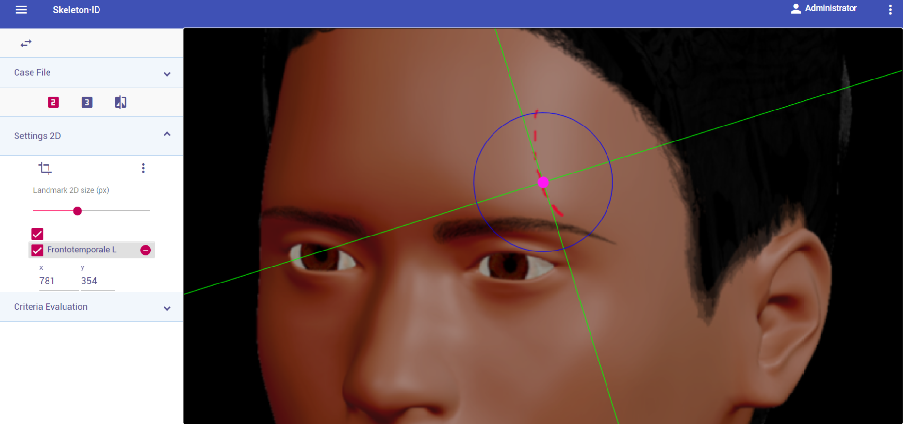 Figure 6. Frontotemporale (left) in oblique view. Approximation in the image.
Observations:
- Avoid marking when the temporal lines are not visible in the photograph.
- According to inter and intraobserver studies (Cummaudo et al. 2013), frontotemporale exhibits high dispersion rates in frontal view. This might be due to the difficulty associated to its location when the temporal lines are not visible.
Photographic examples:

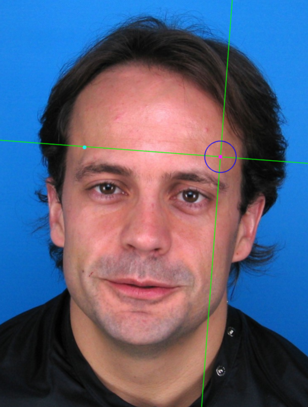
Figure 7. Frontotemporale marking in images where the temporal lines are visible.
Mid-supraorbital
Abbreviature: mso´ L / mso´ R
Laterality: Bilateral
Type: 2
Standardized definition (Caple y Stephan, 2015): Point anteriorly adjacent to the superior orbital rim, at a line that vertically bisects the orbit.
Approximation in the image: Zoom in on the upper half of the face.
Anatomical reference areas: Upper orbital rim.
Guidelines for Skeleton·ID frontal view marking:
Place mid-supraorbital on the most inferior point of the upper orbital rim, in the median plane of the eye orbit. The vertical auxiliary line should be placed on this plane (not necessarily coinciding with the pupil) and the horizontal auxiliary line should be in contact with the inferior border of the supraorbital rim (anterior region of the superior border of the orbit). Follow the same procedure to place the contralateral point.
 Figure 8. Mid-supraorbital (left and right) in frontal view. General shot of the image.
 Figure 9. Mid-supraorbital (left and right) in frontal view. Approximation in the image.
Guidelines for Skeleton·ID lateral view marking:
Place mid-supraorbital on the most anterior point of the upper orbital rim in lateral view. The horizontal auxiliary line should be placed on the upper border of the orbital rim (usually underneath the eyebrow) and the vertical auxiliary line should be in contact with the most anterior point of the border of the supraorbital rim. Follow the same procedure to place the contralateral point.
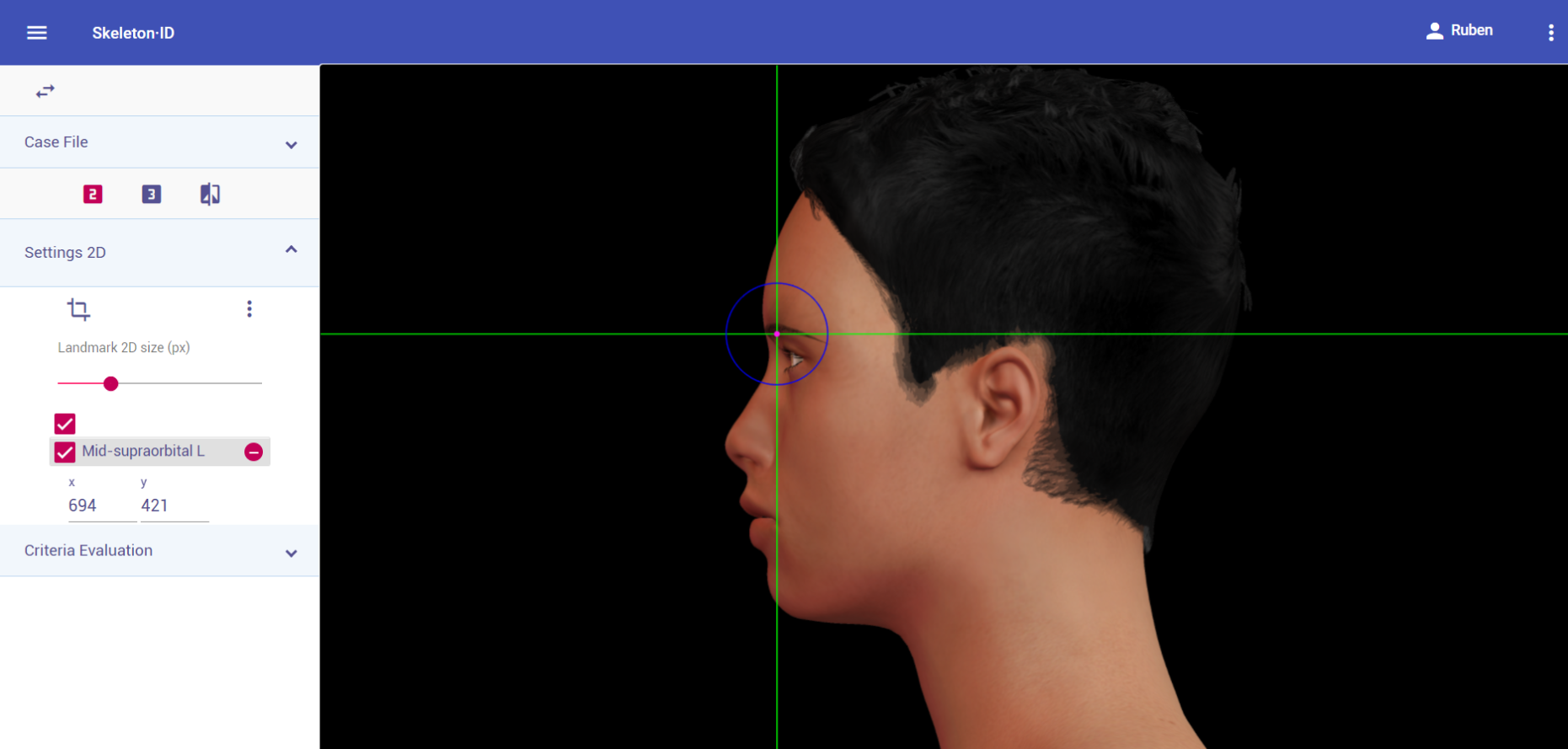 Figure 10. Mid-supraorbital (left) in lateral view. General shot of the image.
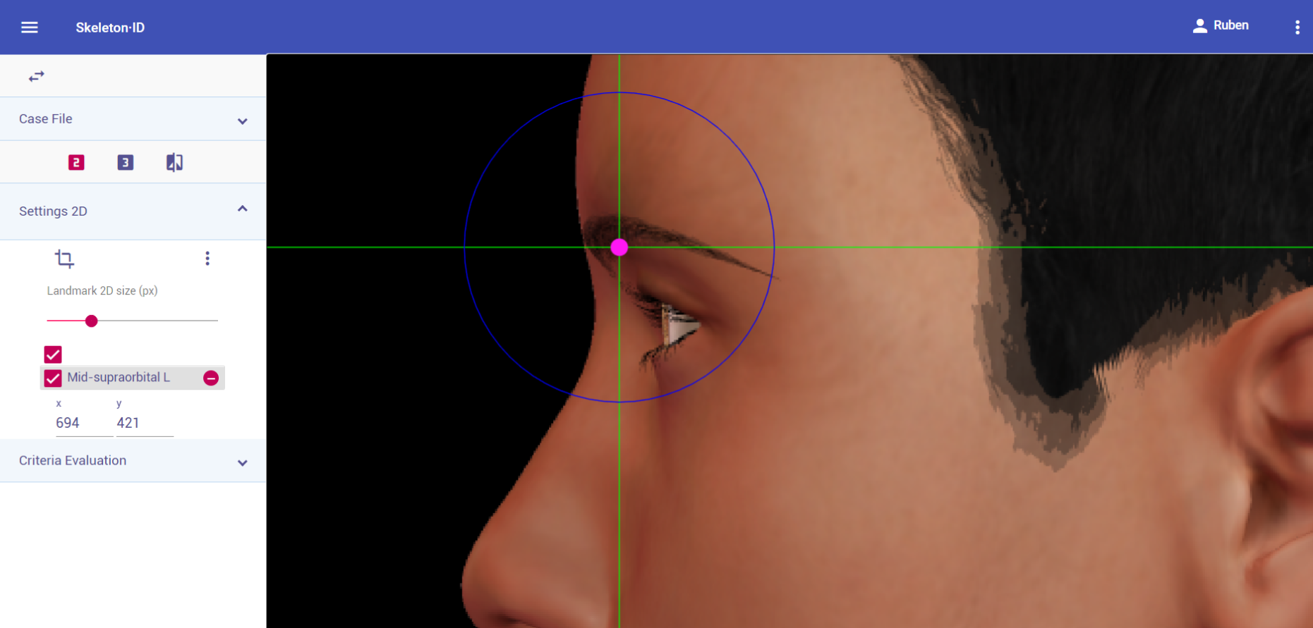 Figure 11. Mid-supraorbital (left) in lateral view. Approximation in the image.
Guidelines for Skeleton·ID oblique view marking:
Place mid-supraorbital on the most inferior point of the upper orbital rim, in the median plane of the eye orbit. The horizontal auxiliary line should be placed on the upper border of the orbital rim (usually underneath the eyebrow) and the vertical auxiliary line should be in the median plane of the eye orbit. Note that depending on the face pose and orientation, it may be necessary to rotate the axis of the auxiliary line to accommodate the landmark. Follow the same procedure to place the contralateral point.
 Figure 12. Mid-supraorbital (left) in oblique view. General shot of the image.
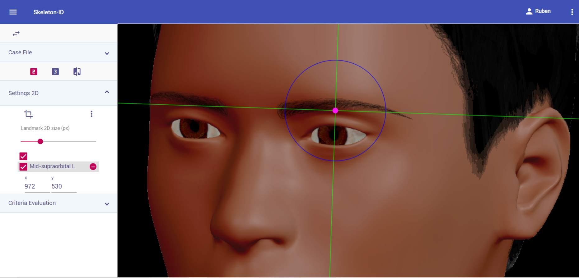 Figure 13. Mid-supraorbital (left) in oblique view. Approximation in the image.
Photographic examples:
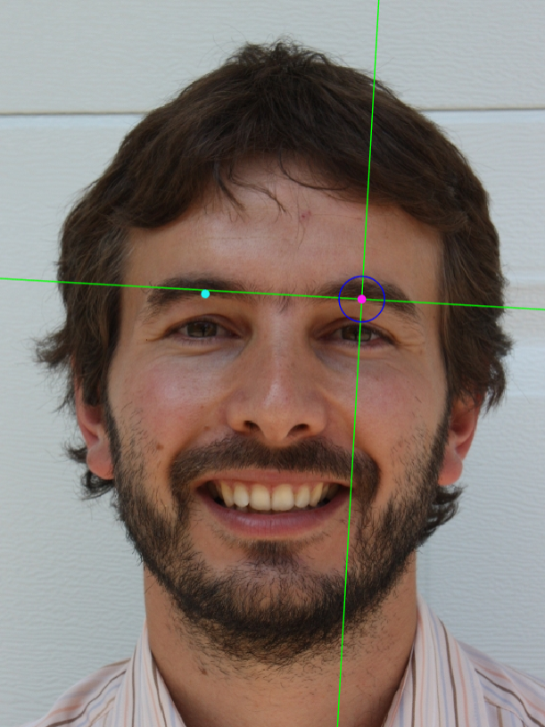
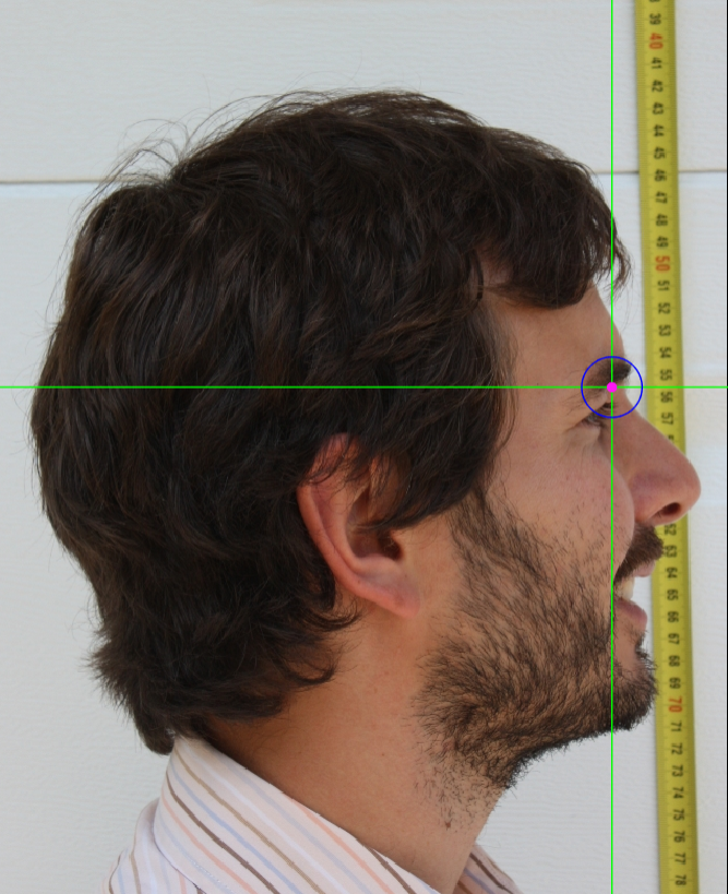
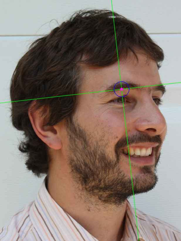 Figure 14. Mid-supraorbital marking on a photograph in frontal view (left), lateral view (center) and oblique view (right).
Frontozygomaticus
Abbreviature: fz´ L / fz´ R
Laterality: Bilateral
Type: 3
Standardized definition (Caple y Stephan, 2015): Most lateral point on the frontozygomatic suture, identified by palpation of the suture line at the superolateral corner of the orbit.
Approximation in the image: Zoom in on the upper half of the face.
Anatomical reference areas: Upperorbital rim.
Guidelines for Skeleton·ID frontal view marking:
It can be very challenging to accurately place this landmark, due to the fact that it is usually located through palpation on the frontozygomatic suture. Generally, the suture is underneath the end of the tail of the eyebrow. Place frontozygomaticus at this region, moving the vertical auxiliary line towards the most lateral point of the eyebrow tail and the horizontal line in contact with the inferior border. Follow the same procedure for the contralateral point.
 Figure 15. Frontozygomaticus (left and right) in frontal view. General shot of the image.
 Figure 16. Frontozygomaticus (left and right) in frontal view. Approximation in the image.
Guidelines for Skeleton·ID lateral view marking:
It can be very challenging to accurately place this landmark, due to the fact that it is usually located through palpation on the frontozygomatic suture. Generally, the suture is underneath the end of the tail of the eyebrow. Place frontozygomaticus at this region, moving the vertical auxiliary line towards the most lateral point of the eyebrow tail and the horizontal line in contact with the inferior border. Note that the contralateral point cannot be estimated.
 Figure 17. Frontozygomaticus (left) in lateral view. General shot of the image.
 Figure 18. Frontozygomaticus (left) in lateral view. Approximation in the image.
Guidelines for Skeleton·ID oblique view marking:
It can be very challenging to accurately place this landmark, due to the fact that it is usually located through palpation on the frontozygomatic suture. Generally, the suture is underneath the end of the tail of the eyebrow. Place frontozygomaticus at this region, moving the vertical auxiliary line towards the most lateral point of the eyebrow tail and the horizontal line in contact with the inferior border. Note that the contralateral point cannot be estimated in oblique view.
 Figure 19. Frontozygomaticus (left) in oblique view. General shot of the image.
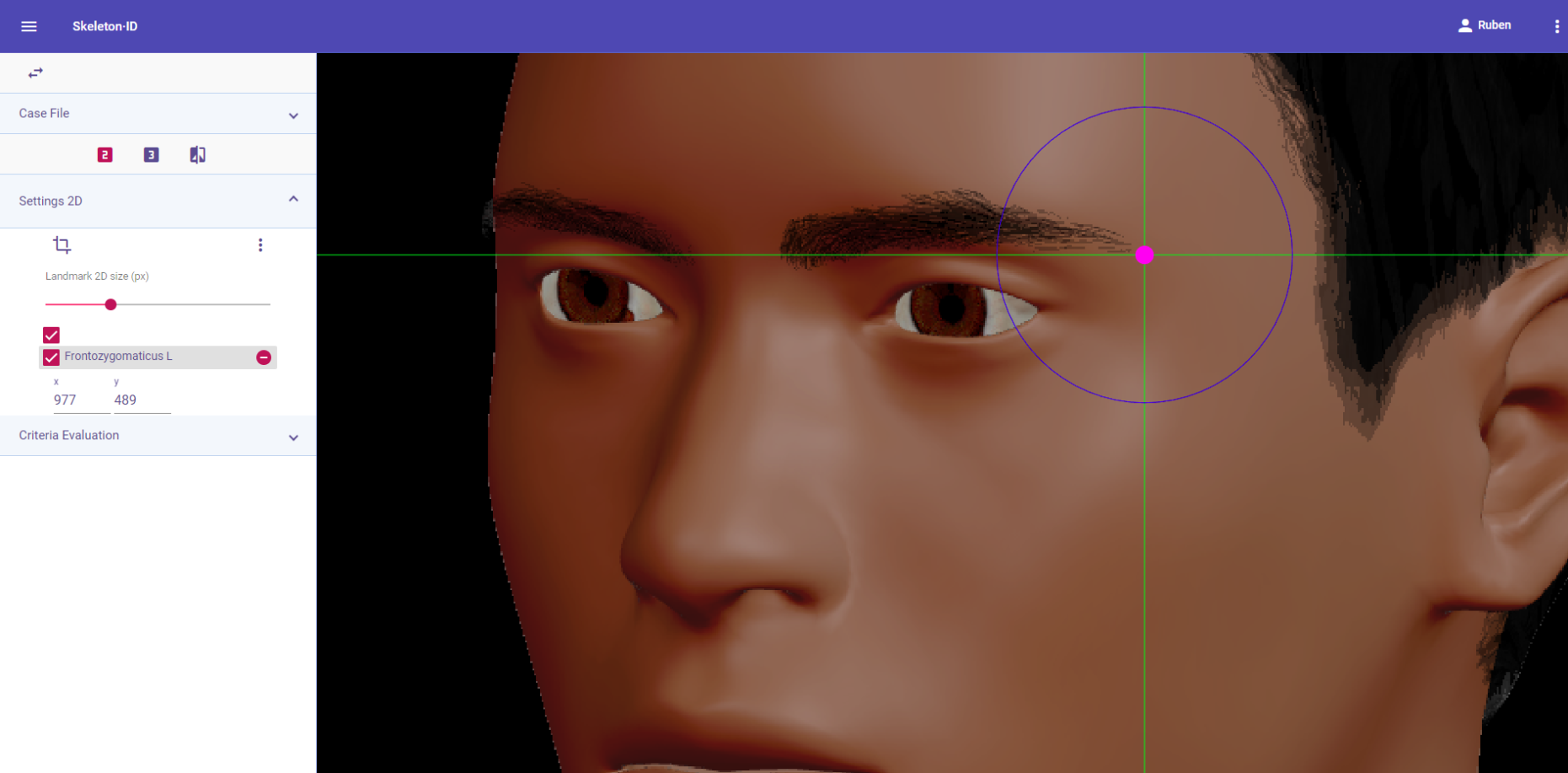 Figure 20. Frontozygomaticus (left) in oblique view. Approximation in the image.
Observations
- Due to frontozygomaticus being a Type 3 landmark, accurately placing this point using only visual references will always be challenging, regardless of the photograph view.
- All modifications present in the eyebrow (waxing, hair removal, hair implants, tattoos, make up, etc.) should be taken into consideration when it is being used as an anatomical reference to place a landmark.
Photographic examples:

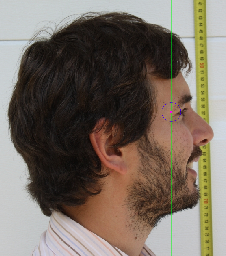
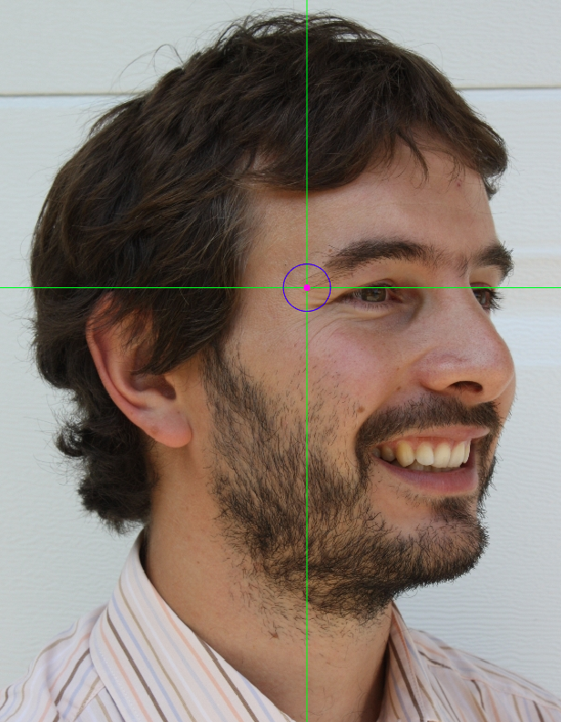 Figure 21. Frontozygomaticus marking on a photograph in frontal view (left), lateral view (center) and oblique view (right).
Exocanthion
Abbreviature: ex´L /ex´R
Laterality: Bilateral
Type: 2
Standardized definition (Caple y Stephan, 2015): Most lateral point of the palpebral fissure, at the outer commissure of the eye; best seen when subject is gazing upward.
Approximation in the image: Zoom in on the corresponding eye.
Anatomical reference areas: Lateral corner of the eye.
Guidelines for Skeleton·ID frontal view marking:
Zoom in on the corresponding eye and place the mouse pointer over the lateral canthus where the upper and lower lash lines converge in frontal view. Place the vertical auxiliary line on the lateral edge of the palpebral fissure and the horizontal auxiliary line where the two lash lines converge. Follow the same procedure for the contralateral landmark.
 Figure 22. Exocanthion (left and right) in frontal view. General shot of the image.
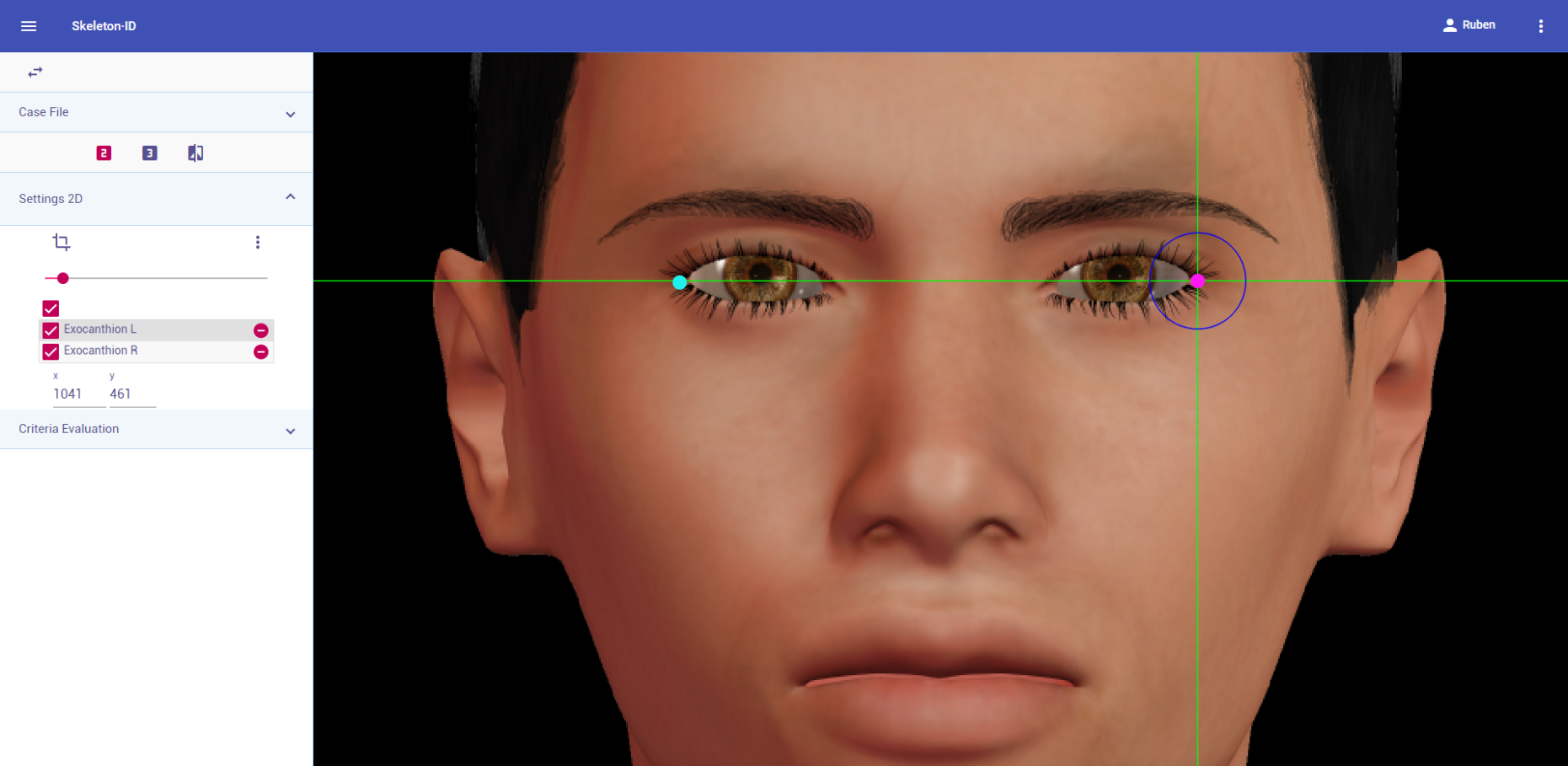 Figure 23. Exocanthion (left and right) in frontal view. Approximation in the image.
Guidelines for Skeleton·ID lateral view marking:
Zoom in on the corresponding eye and place the mouse pointer over the lateral canthus where the upper and lower lashlines converge in frontal view. Place the vertical auxiliary line on the lateral edge of the palpebral fissure and the horizontal auxiliary line where the two lashlines converge. Note that the contralateral landmark cannot be estimated in lateral view.
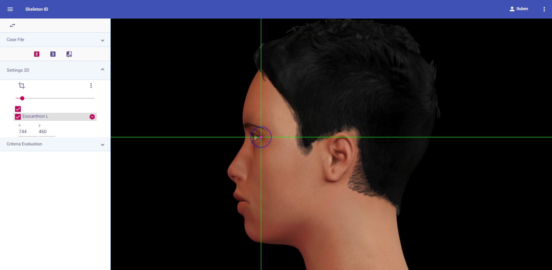 Figure 24. Exocanthion (left) in lateral view. General shot of the image.
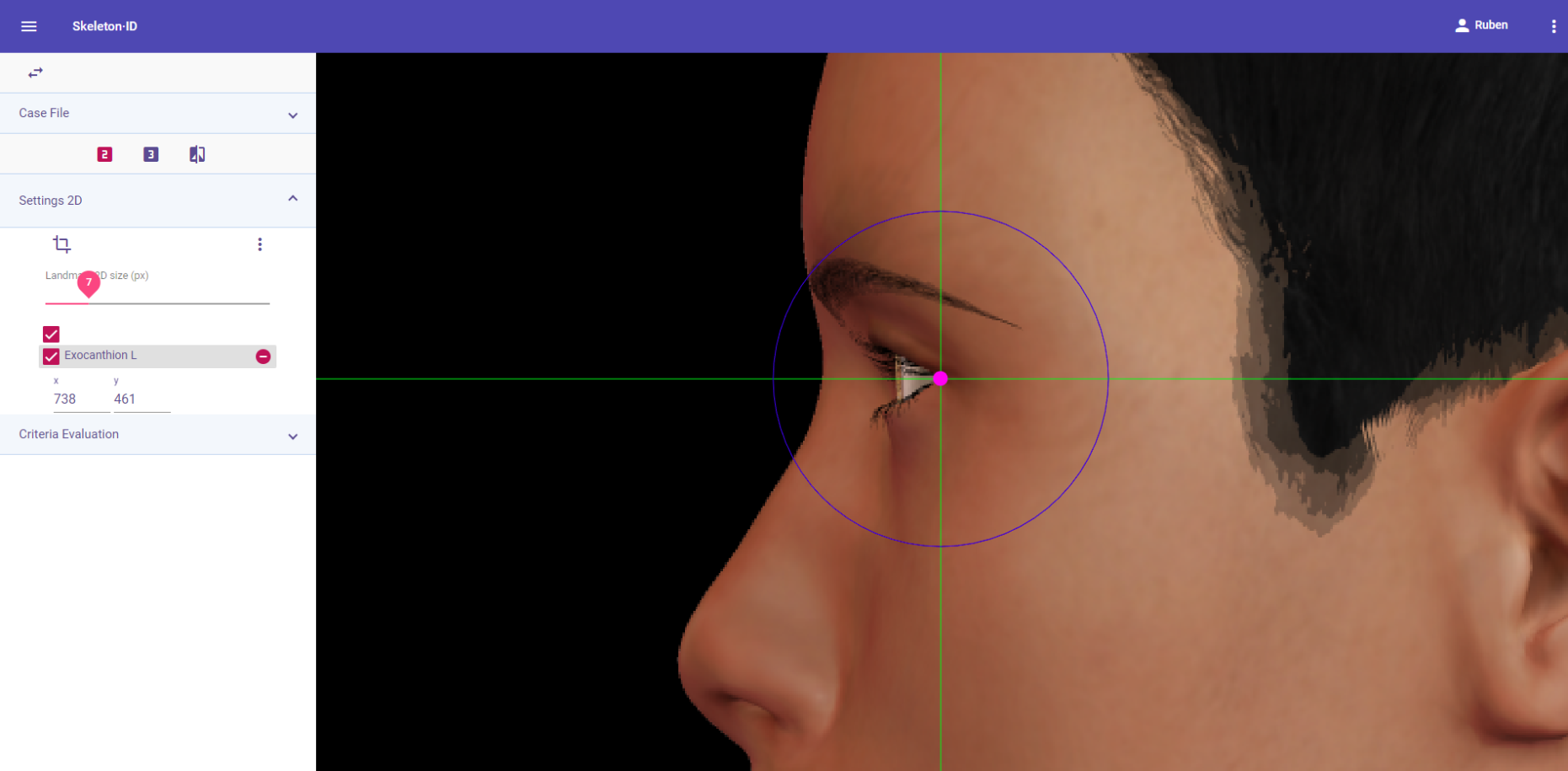 Figure 25. Exocanthion (left) in lateral view. Approximation in the image.
Guidelines for Skeleton·ID oblique view marking:
Zoom in on the corresponding eye and place the mouse pointer over the lateral canthus where the upper and lower lashlines converge in frontal view. Place the vertical auxiliary line on the lateral edge of the palpebral fissure and the horizontal auxiliary line where the two lashlines converge. Note that the rotation of the head in oblique view might hinder the location of the lateral canthus of one of the eyes.
 Figure 26. Exocanthion (left) in oblique view. General shot of the image.
 Figure 27. Exocanthion (left) in oblique view. Approximation in the image.
Observations
- Exocanthion should be placed on the outermost edge of the palpebral fissure and NOT in the waterline, adjacent to the eyeball.
 Figure 28. Examples of the precise marking of exocanthion (green dot) and its inaccurate placement (red dot).
- In cases where the landmark may be covered by lashes, the precise location should be estimated.
 Figure 29. Example of a photograph in which the lateral canthus of the eye is obscured by lashes (left). Estimation of the right exocanthion (right).
- According to interobserver studies (Campomanes-Álvarez et al., 2015), exocanthion can be accurately placed with high frequency (70%) in facial images regardless of the view (frontal, lateral or oblique).
Photographic examples:
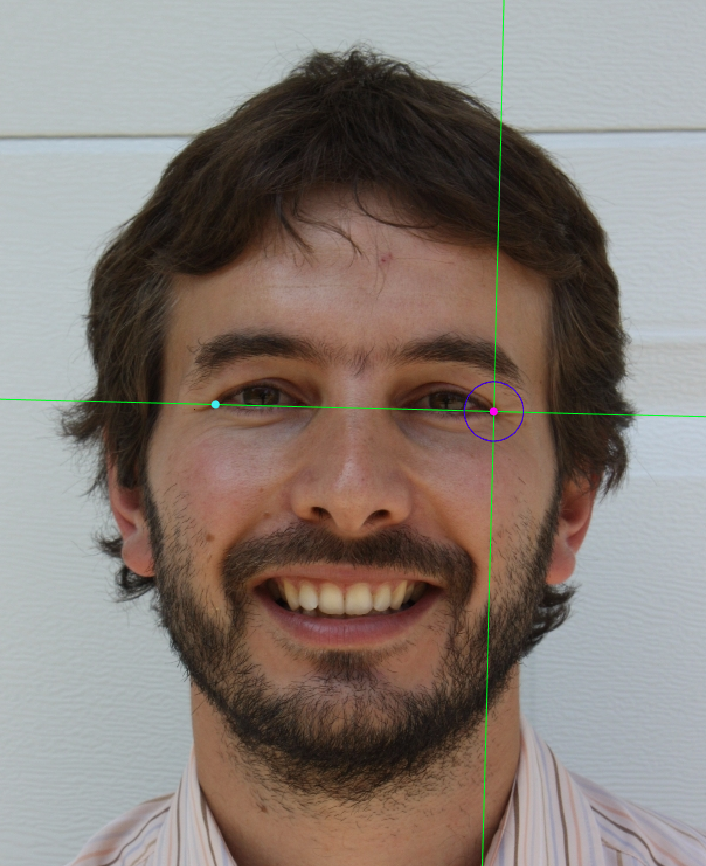
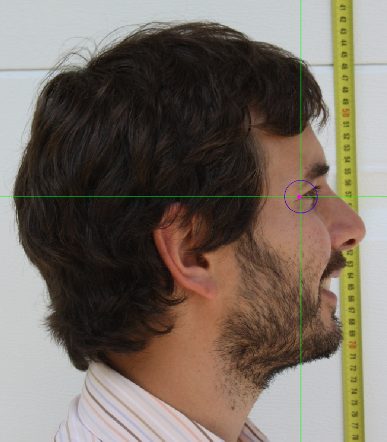
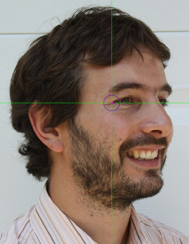 Figure 30. Exocanthion marking on a photograph in frontal view (left), lateral view (center) and oblique view (right)
Endocanthion
Abbreviature: en´L /en´R
Laterality: Bilateral
Type: 1
Standardized definition (Caple y Stephan, 2015): Most medial point of the palpebral fissure, at the inner commissure of the eye; best seen when subject is gazing upward.
Approximation in the image: Zoom in on the corresponding eye.
Anatomical reference areas: Free margin of the eyelids. Lash line.
Guidelines for Skeleton·ID frontal view marking:
Zoom in on the corresponding eye and place the mouse pointer over the medial canthus where the upper and lower lash lines converge in frontal view. Place the vertical auxiliary line on the medial border of the palpebral fissure and the horizontal auxiliary line where the two lash lines converge. Follow the same procedure for the contralateral landmark.
 Figure 31. Endocanthion (left and right) in frontal view. General shot of the image.
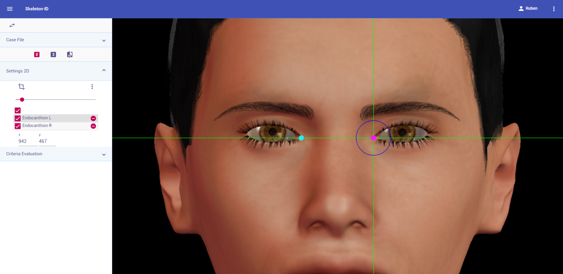 Figure 32. Endocanthion (left and right) in frontal view. Approximation in the image.
Guidelines for Skeleton·ID oblique view marking:
Zoom in on the corresponding eye and place the mouse pointer over the medial canthus where the upper and lower lash lines converge in oblique view. Place the vertical auxiliary line on the medial border of the palpebral fissure and the horizontal auxiliary line where the two lash lines converge. Note that the rotation of the head in oblique view might hinder the location of the medial canthus of one of the eyes.
 Figure 33. Endocanthion (left) in oblique view. General shot of the image.
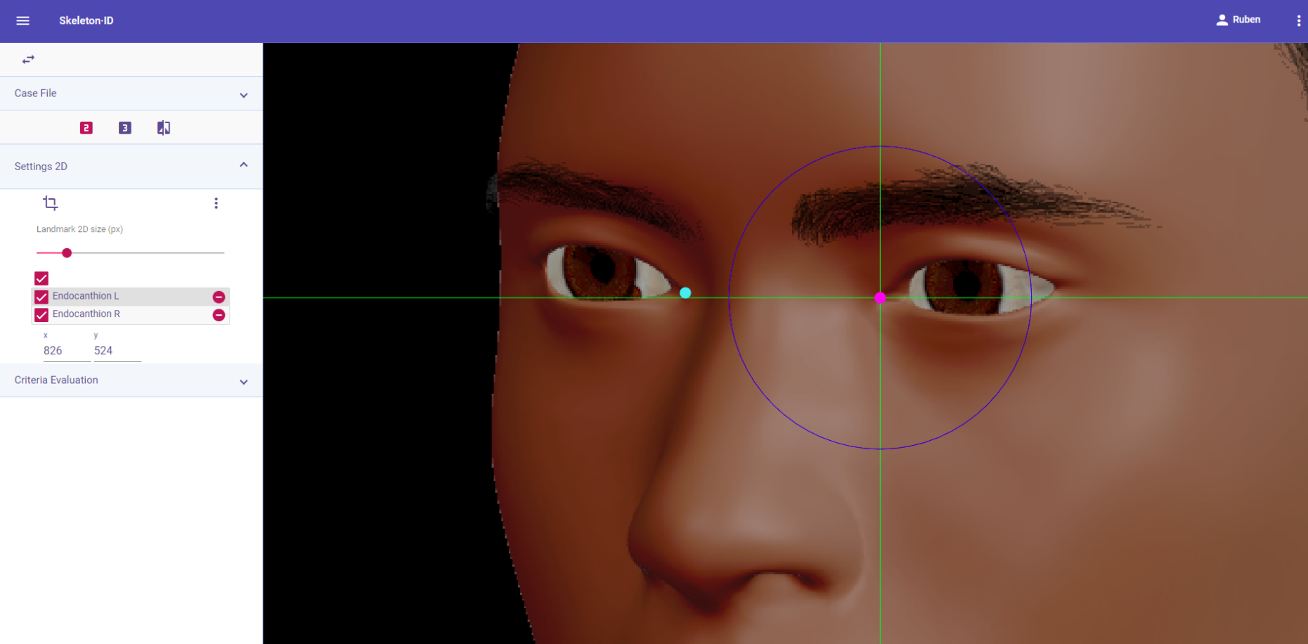 Figure 34. Endocanthion (left) in oblique view. Approximation in the image.
Observations
- Endocanthion should be placed on the border of the medial canthus, right on the palpebral fissure and NOT on the lacrimal caruncle, adjacent to the eyeball.
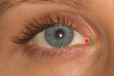 Figure 35. xamples of the precise marking of endocanthion (green dot) and its inaccurate placement (red dot).
- According to interobserver studies (Campomanes-Álvarez et al., 2015), endocanthion can be accurately placed with high frequency (70%) in frontal, lateral or oblique facial images with limitations (concerning the degree of the pose). Cannot be determined in lateral images.
Photographic examples:
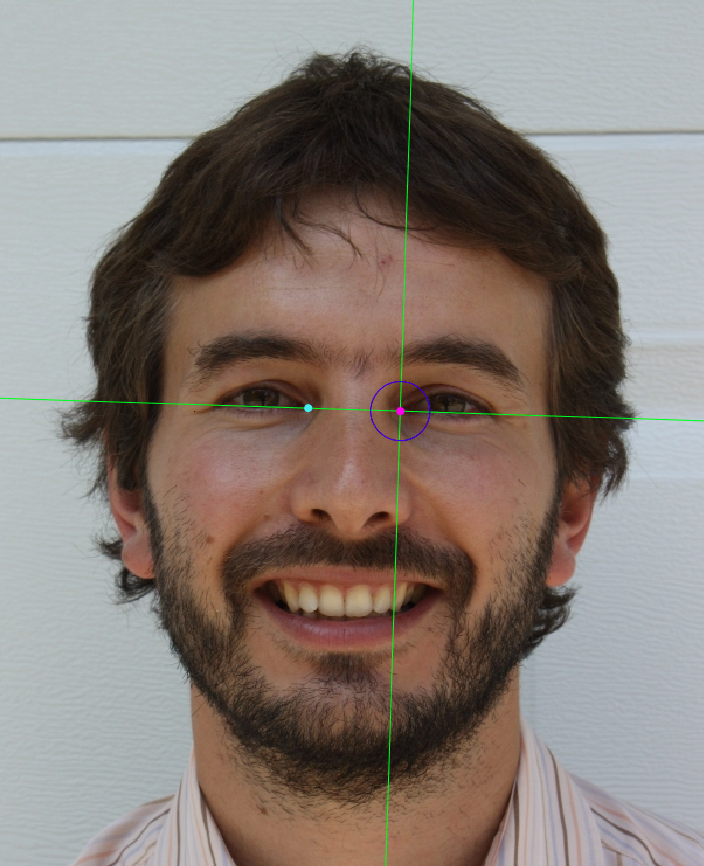

Figure 36. Endocanthion marking on a photograph in frontal view (left) and oblique view (right).
Tragion
Abbreviature: t´ L / t´ R
Laterality: Bilateral
Type: 2
Standardized definition (Caple y Stephan, 2015): Located at the notch above the tragus of the ear (the cartilaginous projection anterior to the external auditory canal), where the upper edge of the cartilage disappears into the skin of the face.
Approximation in the image: Zoom in on the upper half of the face.
Anatomical reference areas: Auricular region.
Guidelines for Skeleton·ID frontal view marking:
Place tragion on the ear tragus, where the rostral end of the cartilage disappears into the skin of the face in frontal view. Place the vertical auxiliary line in the lateral contour of the notch above the tragus and the horizontal auxiliary line over the most superior point of the tragus, where the cartilage disappears into the skin of the face. Follow the same procedure for the contralateral landmark.
 Figure 37. Tragion (left and right) in frontal view. General shot of the image.
 Figure 38. Tragion (left and right) in frontal view. Approximation in the image.
Guidelines for Skeleton·ID lateral view marking:
Place tragion on the ear tragus, where the rostral end of the cartilage disappears into the skin of the face in oblique view. Place the vertical auxiliary line in the lateral contour of the notch above the tragus and the horizontal auxiliary line over the most superior point of the tragus, where the cartilage disappears into the skin of the face. Note that the contralateral landmark cannot be estimated in lateral view.
 Figure 39. Tragion (left) in lateral view. General shot of the image.
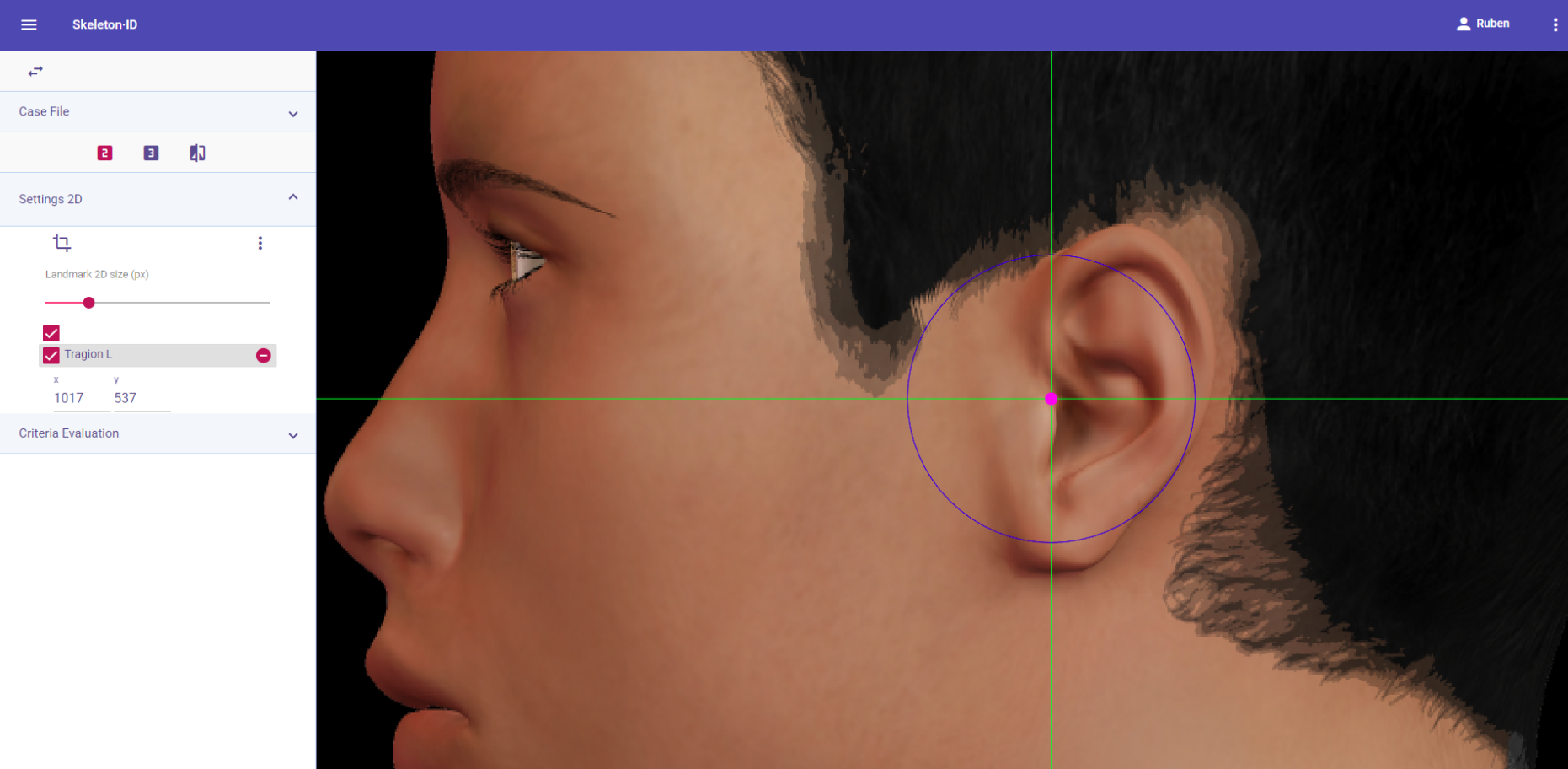 Figure 40. Tragion (left) in lateral view. Approximation in the image.
Guidelines for Skeleton·ID oblique view marking:
Place tragion on the ear tragus, where the rostral end of the cartilage disappears into the skin of the face in oblique view. Place the vertical auxiliary line in the lateral contour of the notch above the tragus and the horizontal auxiliary line over the most superior point of the tragus, where the cartilage disappears into the skin of the face. Note that the contralateral landmark cannot be estimated in oblique view.
 Figure 41. Tragion (left) in oblique view. General shot of the image.
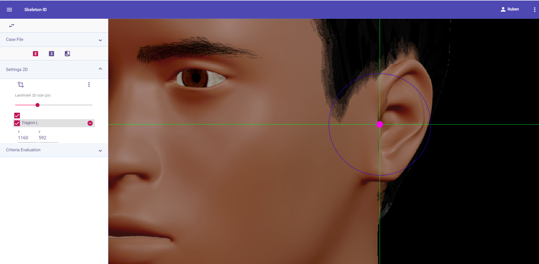 Figure 42. Tragion (left) in oblique view. Approximation in the image.
Observations
- Avoid marking in subjects in which the tragus of the ear is obscured by hair.
 Figure 43. Example of a photograph where the subject’s hair is obscuring partially the ear, preventing from marking tragion.
Photographic examples:

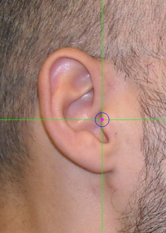
 Figure 44. Tragion marking on a photograph in frontal view (left), lateral view (center) and oblique view (right).
Zygion
Abbreviature: zy´ L / zy´ R
Laterality: Bilateral
Type: 3
Standardized definition (Caple y Stephan, 2015): Most lateral point overlying each zygomatic arch, identified as the point of máximum bizygomatic breadth of the face.
Approximation in the image: Zoom in on the middle third of the face.
Anatomical reference areas:
- Lateral facial contour.
- Ear (tragus and helix root).
Guidelines for Skeleton·ID frontal view marking:
Place zygion on the most lateral point of each side of the width of the face in frontal view. The horizontal auxiliary line should be in the area of maximum width of the face (usually the root of the helix and the tragus) and the vertical auxiliary line should be on the edge of the lateral contour of the zygomatic arch. Follow the same procedure for the contralateral landmark.
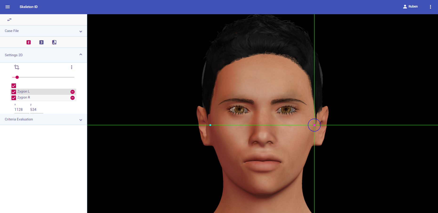 Figure 45. Zygion (left and right) in frontal view. General shot of the image.
 Figure 46. Zygion (left and right) in frontal view. Approximation in the image.
Guidelines for Skeleton·ID lateral view marking:
Place zygion on the rostral edge of the root of helix and tragus. The vertical auxiliary line should be anterior to the hairline (in the facial skin) and the horizontal auxiliary line should be between the root of helix and the tragus, aligning with the inferior orbital rim. Note that this landmark exhibits high variability in its placement in lateral view images due to the uncertainty associated to its estimation. It may be necessary to rotate the axis of the auxiliary lines in order to place them in the reference area and align them to the inferior orbital rim.
 Figure 47. Zygion (left) in lateral view. General shot of the image.
 Figure 48. Zygion (left) in lateral view. Approximation in the image.
Guidelines for Skeleton·ID oblique view marking:
Place zygion on the rostral edge of the root of helix and tragus. The vertical auxiliary line should be anterior to the hairline (in the facial skin) and the horizontal auxiliary line should be between the root of helix and the tragus, aligning with the inferior orbital rim. Note that this landmark exhibits high variability in its placement in oblique view images due to the uncertainty associated to its estimation. It may be necessary to rotate the axis of the auxiliary lines in order to place them in the reference area and align them to the inferior orbital rim.
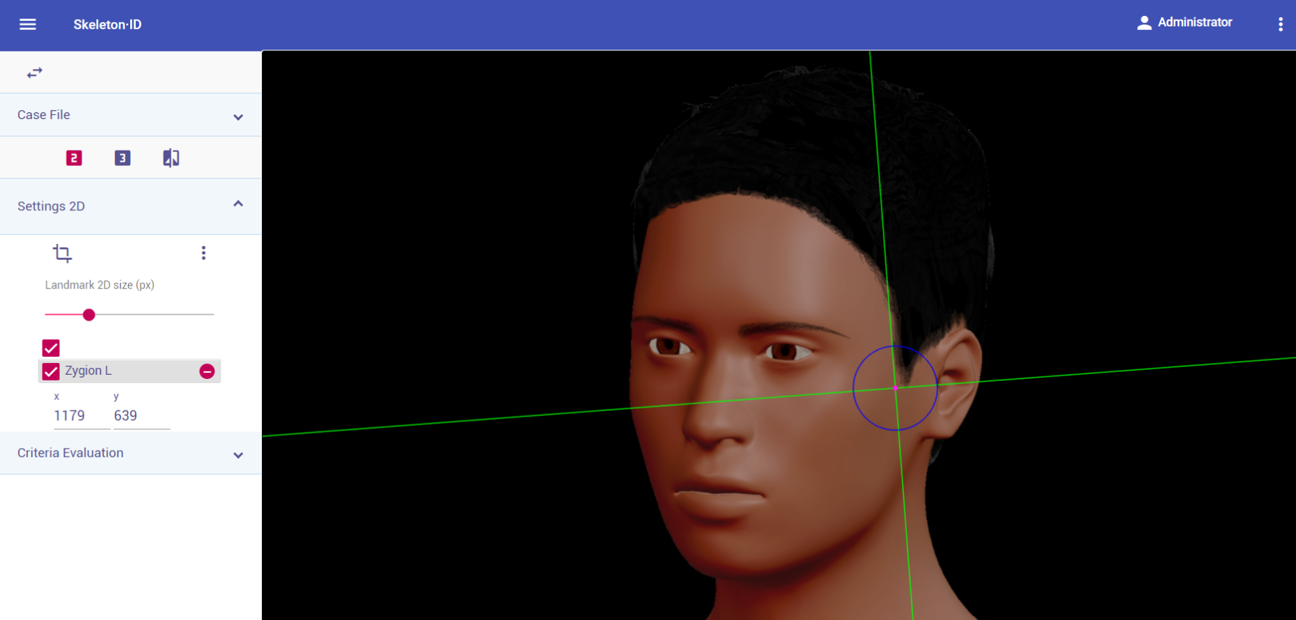 Figure 49. Zygion (left) in oblique view. General shot of the image.
 Figure 50. Zygion (left) in oblique view. Approximation in the image.
Observations
- It can be very challenging to accurately place this landmark, due to the fact that it is usually located through palpation (Type 3) on the zygomatic arch and has to be estimated on photographs. Since the eyes are usually aligned with the upper region of the ears in photographs, the upper limit of the area of zygion should be the helix insertion, and the lower limit, the median height of the tragus) homologue in the face to the temporal process of the zygomatic bone, right above the external auditory meatus).
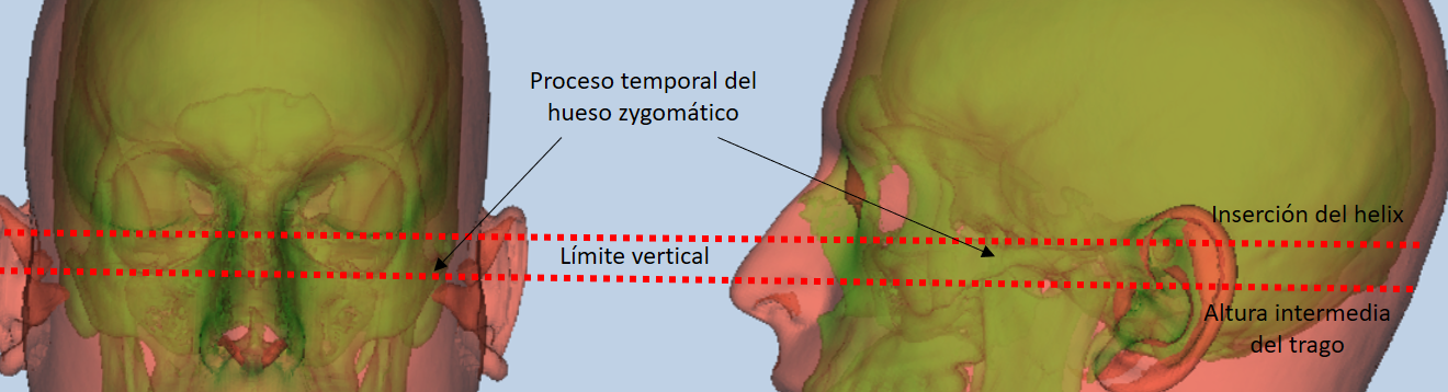 Figure 51. Facial region and references for zygion estimation.
- According to inter and intraobserver studies (Cummaudo et al., 2013; Campomanes-Álvarez et al., 2015), the dispersion of zygion is high regardless of the view of the image, due to the fact that it is a point located through palpation.
Photographic examples:
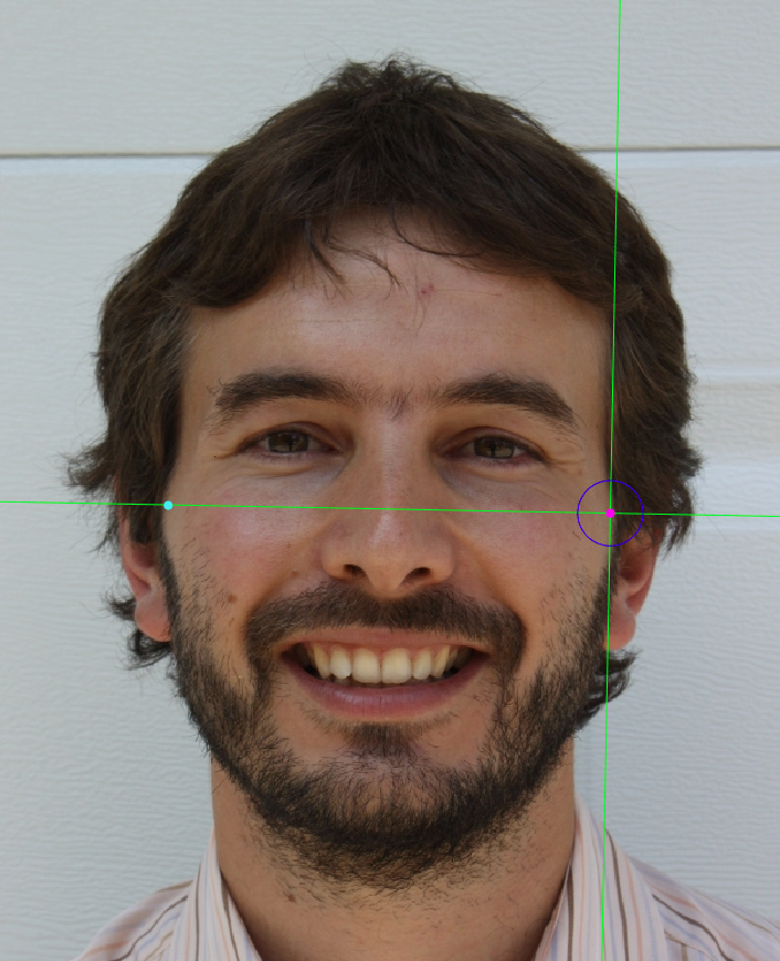
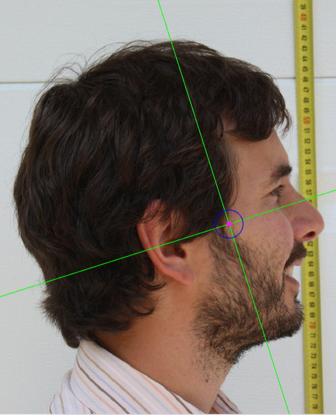
 Figure 52. Zygion marking on a photograph in frontal view (left), lateral view (center) and oblique view (right).
Alare
Abbreviature: al´ L / al´ R
Laterality: Bilateral
Type: 3
Standardized definition (Caple y Stephan, 2015): The most lateral point on the nasal ala.
Approximation in the image: Zoom in on the middle third of the face or the complete face.
Anatomical reference areas: Lateral region of the nasal alae.
Guidelines for Skeleton·ID frontal view marking:
Place alare on the most lateral point of the nasal alae in frontal view. The vertical auxiliary line should be placed on the most lateral point of the nasal ala (it may be necessary to rotate the axis of the auxiliary lines to determine this point), and the horizontal auxiliary line should be placed on the maximum width of the nasal alae. Follow the same procedure for the contralateral landmark, which may not be at the same height, which means it may be necessary to rotate the horizontal line to find the most accurate alignment.
 Figure 53. Alare (left and right) in frontal view. General shot of the image.
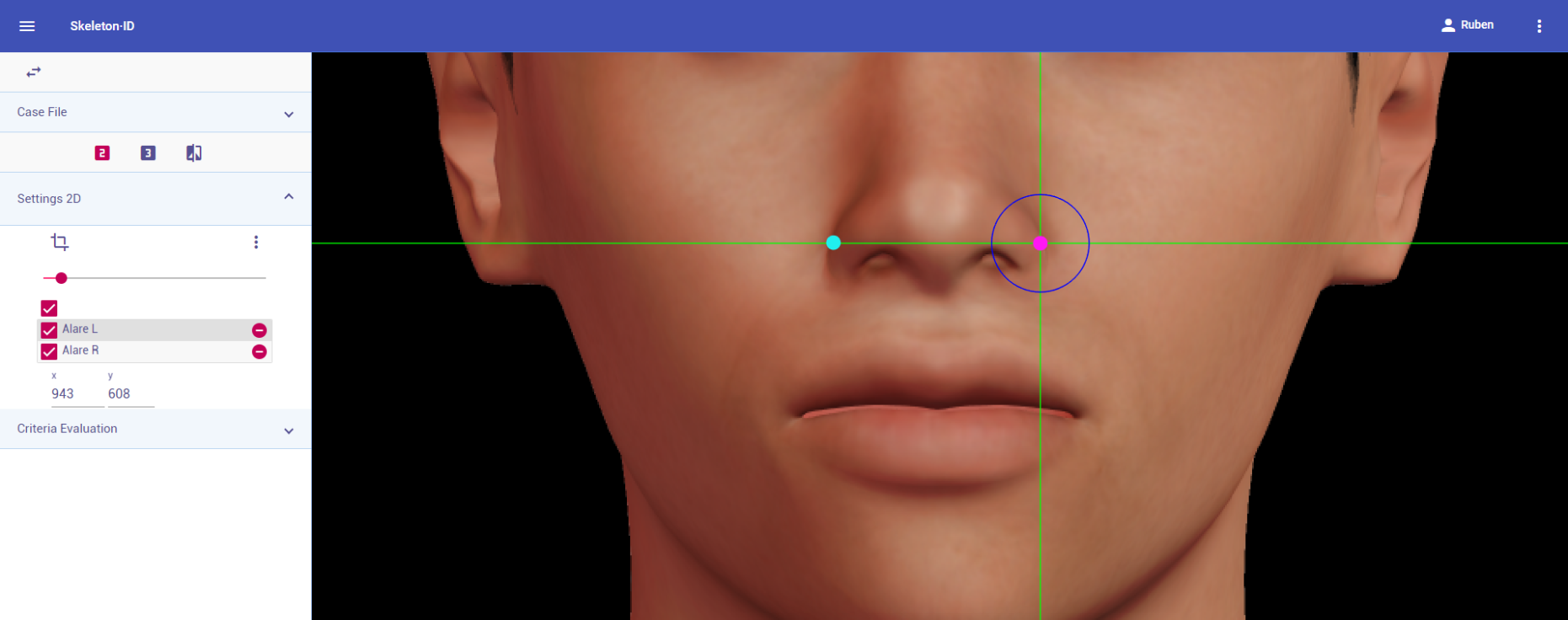 Figure 54. Alare (left and right) in frontal view. Approximation in the image.
Guidelines for Skeleton·ID lateral view marking:
Place alare on the most lateral point of the nasal alae in lateral view. The vertical auxiliary line should be placed on the lateral of the nasal ala and the horizontal auxiliary line should be placed on the most external point. Note that the landmark should be on the nasal ala and not on the nasal fold.
 Figure 55. Alare (left) in lateral view. General shot of the image.
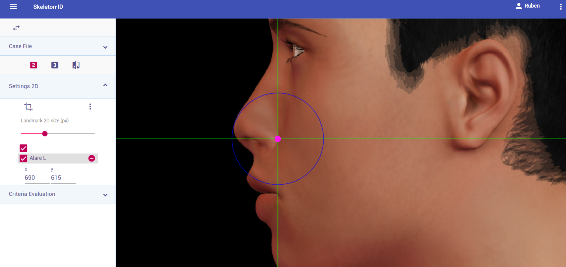 Figure 56. Alare (left) in lateral view. Approximation in the image.
Guidelines for Skeleton·ID oblique view marking:
Place alare on the most lateral point of the nasal alae in oblique view. The vertical auxiliary line should be placed on the lateral of the nasal ala and the horizontal auxiliary line should be placed on the most external point. Note that the landmark should be on the nasal ala and not on the nasal fold.
 Figure 57. Alare (left) in oblique view. General shot of the image.
 Figure 58. Alare (left) in oblique view. Approximation in the image.
Observations
- Note that the right and left alare are not always at the same height.
 Figure 59. Example o fan asymmetric nasal base. The left alare is lower than the right alare.
- According to interobserver studies (Campomanes-Álvarez et al., 2015), alare can be accurately placed with high frequency (70%) in frontal and oblique view facial images, with limitations related to the degree of the pose. It can be challenging to accurately locate in lateral view images (the external region of the nasal ala may be hidden by the cheek).
Photographic examples:
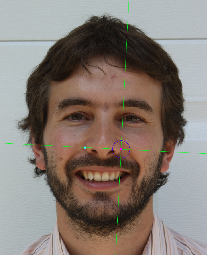

 Figure 60. Alare marking on a photograph in frontal view (left), lateral view (center) and oblique view (right).
Cheilion
Abbreviature: ch´ L / ch´ R
Laterality: Bilateral
Type: 2
Standardized definition (Caple y Stephan, 2015): Outer corners of the mouth where the outer edges of the upper and lower vermillions meet.
Approximation in the image: Zoom in on the lower half of the face.
Anatomical reference areas:
- Labial commissures.
- Lateral regions of the vermillion borders.
Guidelines for Skeleton·ID frontal view marking:
Place cheilion on the outer corners of the mouth in frontal view. The vertical auxiliary line should be placed on the commisure of the lips and the horizontal line should be placed at the point where the upper and lower vermillion borders meet. Follow the same procedure for the contralateral landmark, which may not be at the same height.
 Figure 61. Cheilion (left and right) in frontal view. General shot of the image.
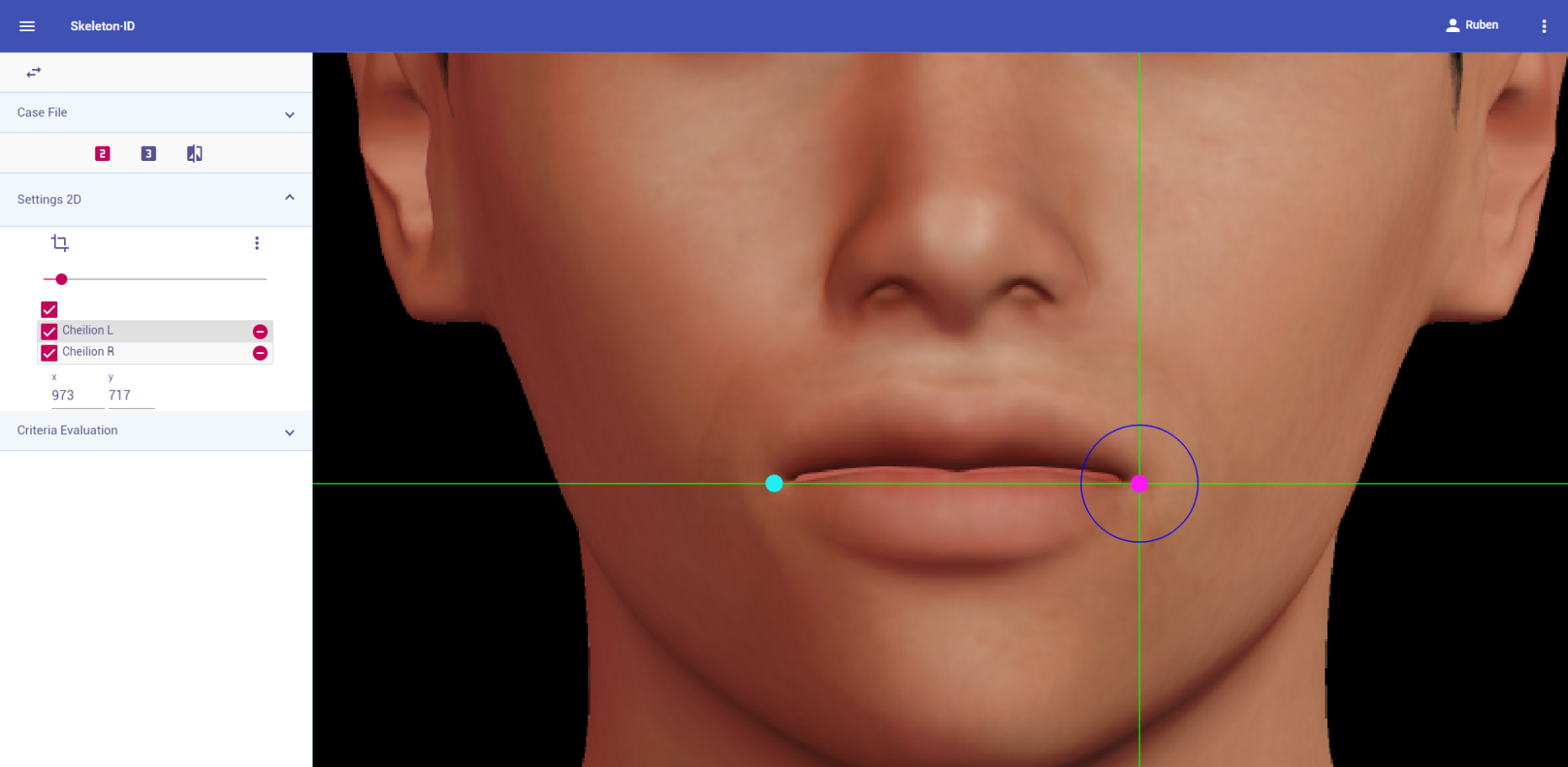 Figure 62. Cheilion (left and right) in frontal view. Approximation in the image.
Guidelines for Skeleton·ID lateral view marking:
Place cheilion on the outer corners of the mouth in lateral view. The vertical auxiliary line should be placed on the commisure of the lips and the horizontal line should be placed at the point where the upper and lower vermillion borders meet. Note that the contralateral landmark cannot be estimated in lateral view.
 Figure 63. Cheilion (left) in lateral view. General shot of the image.
 Figure 64. Cheilion (left) in lateral view. Approximation in the image.
Guidelines for Skeleton·ID oblique view marking:
Place cheilion on the outer corners of the mouth in oblique view. The vertical auxiliary line should be placed on the commisure of the lips and the horizontal line should be placed at the point where the upper and lower vermillion borders meet. Note that the contralateral landmark cannot be estimated in oblique view.
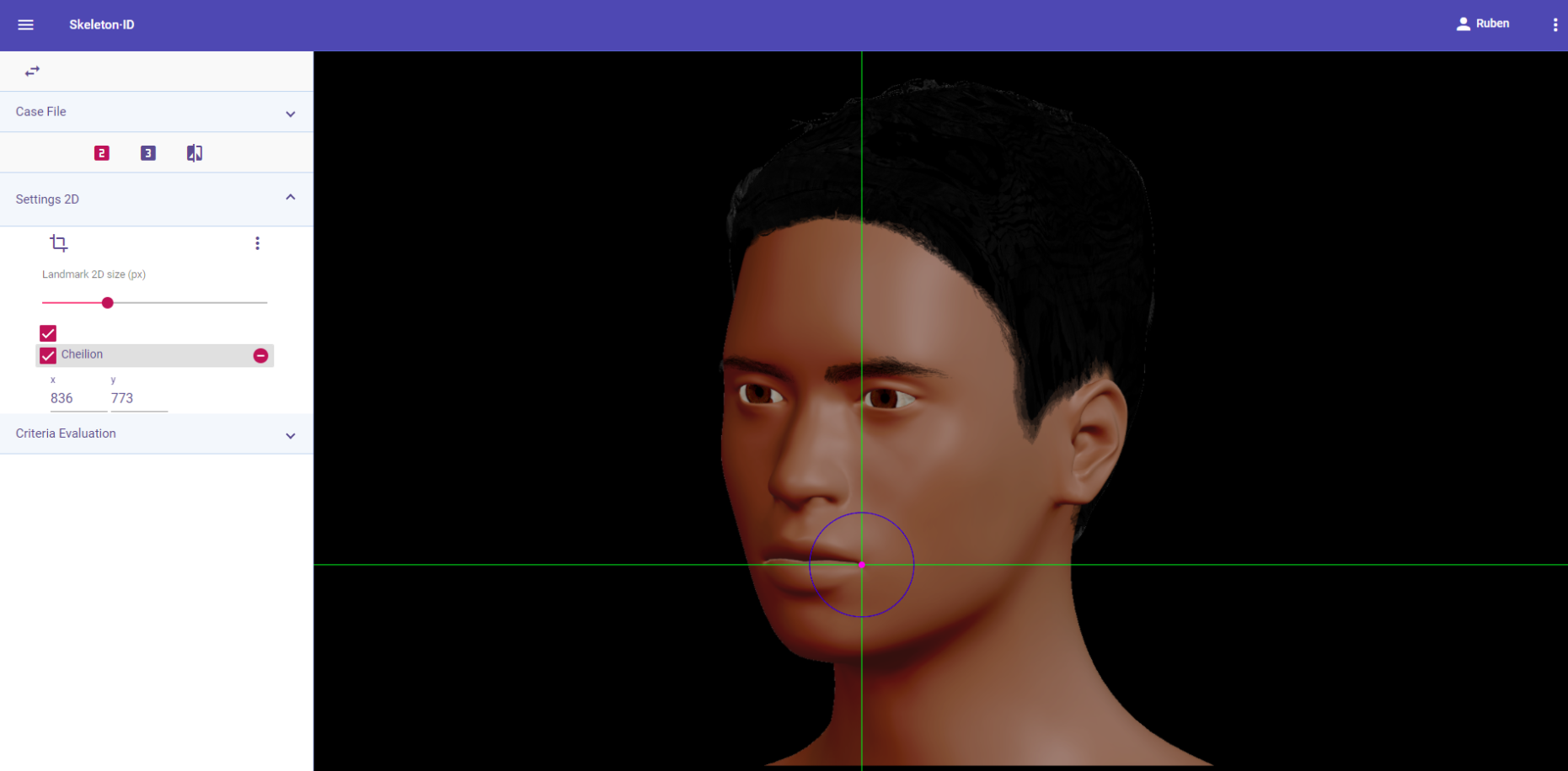 Figure 65. Cheilion (left) in oblique view. General shot of the image.
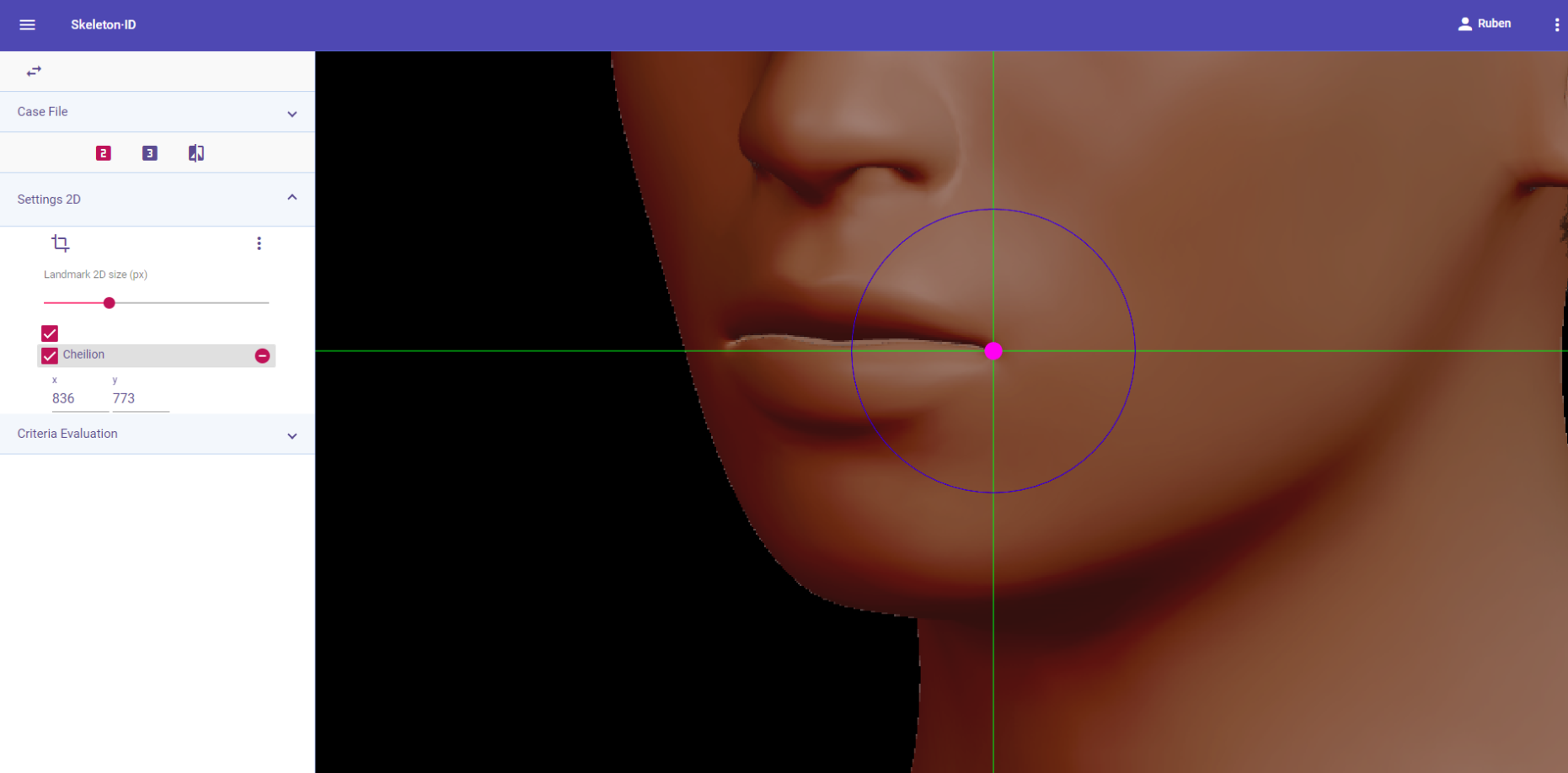 Figure 66. Cheilion (left) in oblique view. Approximation in the image.
Observations
- When the upper and lower vermillion are in different regions of the rima oris (labial fissure), place this landmark where the rima oris meets the most lateral point of the vermillion border.
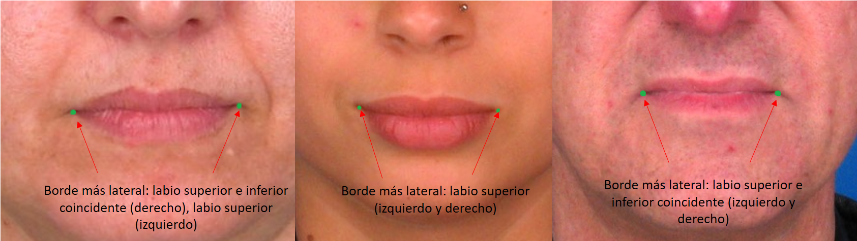 Figure 67. Examples of subjects with different junction points of the upper and lower lips in the rima oris.
Photographic examples:

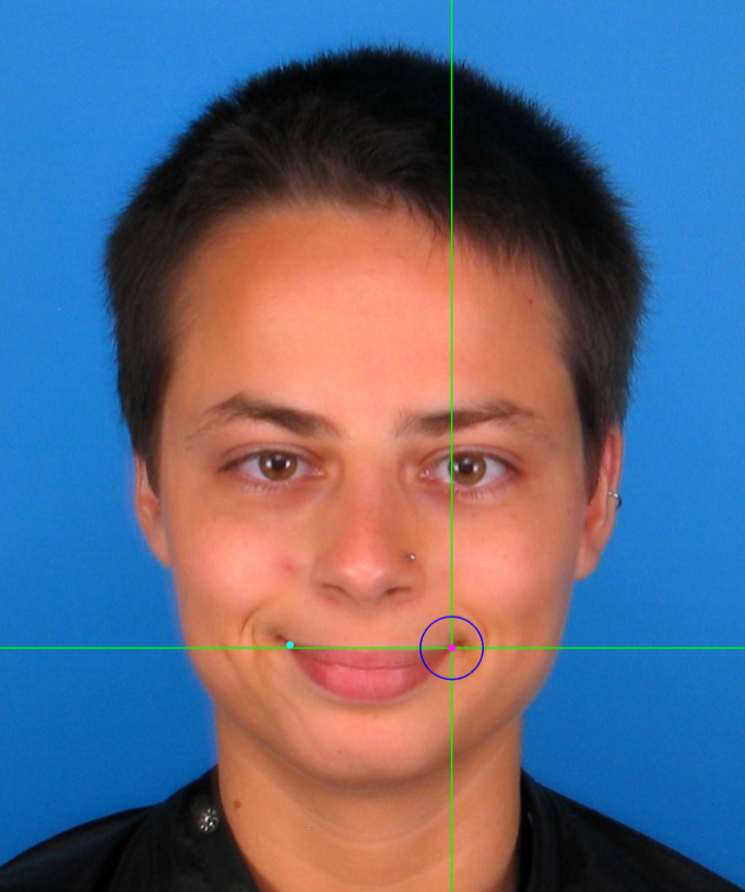
 Figure 68. Examples of cheilion marking on frontal view photographs.
Gonion
Abbreviature: go´ L / go´ R
Laterality: Bilateral
Type: 3
Standardized definition (Caple y Stephan, 2015): Most lateral point on the mandibular angle, adjacent to go, identified by palpation.
Approximation in the image: Zoom in on the lower half of the face.
Anatomical reference areas: Lateral contour of the mandible.
Guidelines for Skeleton·ID frontal view marking:
Place gonion on the mandibular angle in frontal view. Place the horizontal auxiliary line over the lower lip and the vertical auxiliary line on the edge of the lateral contour of the mandible. Follow the same procedure for the contralateral landmark. It can be challenging to accurately locate this landmark due to the fact that it is usually located through palpation (Type 3) on the mandibular angle, and has to be estimated on photographs.
 Figure 69. Gonion (left and right) in frontal view. General shot of the image.
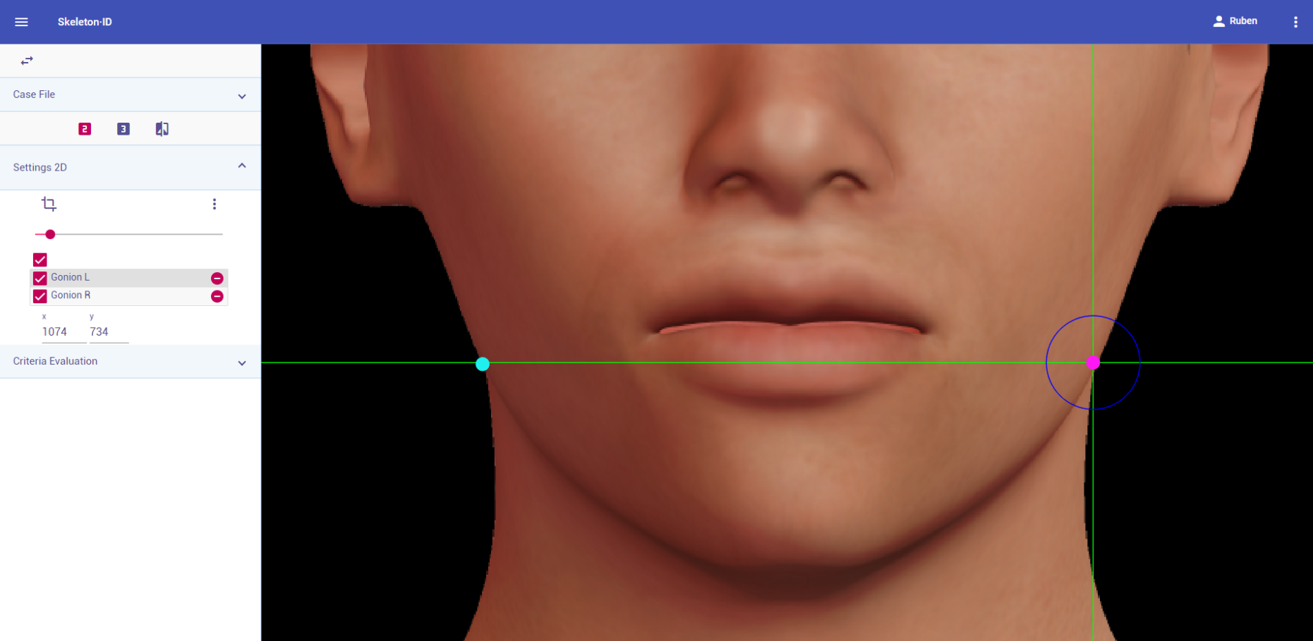 Figure 70. Gonion (left and right) in frontal view. Approximation in the image.
Guidelines for Skeleton·ID lateral view marking:
Place gonion on the mandibular angle in lateral view. Rotate the vertical auxiliary line to match the lateral contour of the face and place the horizontal auxiliary line at the intersection with the inferior contour. It can be challenging to accurately locate this landmark due to the fact that it is usually located through palpation (Type 3) on the mandibular angle and has to be estimated on photographs.
 Figure 71. Gonion (left) in lateral view. General shot of the image.
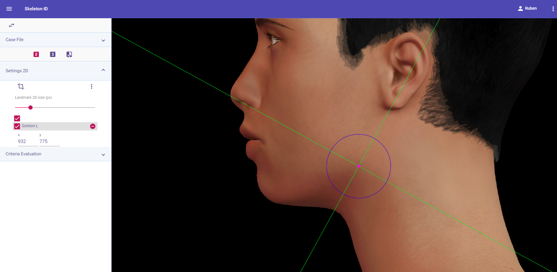 Figure 72. Gonion (left) in oblique view. General shot of the image.
Guidelines for Skeleton·ID oblique view marking:
Place gonion on the mandibular angle in oblique view. Rotate the vertical auxiliary line to match the lateral contour of the face and place the horizontal auxiliary line at the intersection with the inferior contour. It can be challenging to accurately locate this landmark due to the fact that it is usually located through palpation (Type 3) on the mandibular angle, and has to be estimated on photographs.
 Figure 73. Gonion (left) in oblique view. General shot of the image.
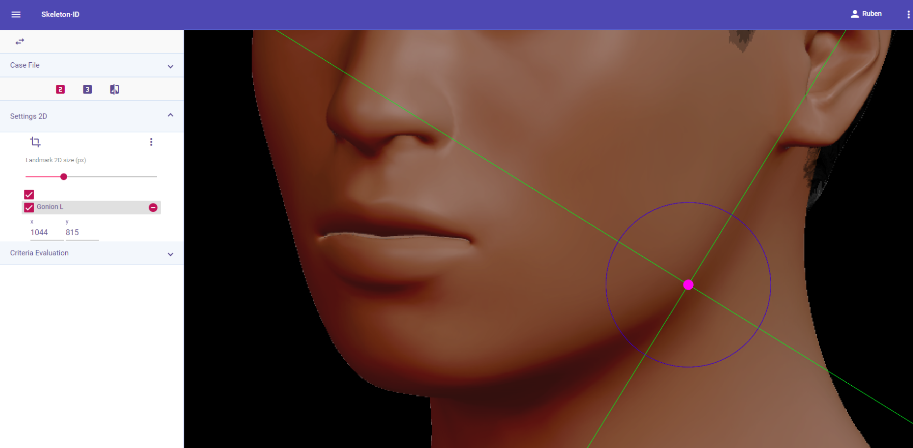 Figure 74. Gonion (left) in oblique view. Approximation in the image.
Observations
- Due to the fact that gonion is identified by palpation (Type 3), it has to be estimated in photographs, which means its location tends to be less accurate regardless of the view (frontal, lateral or oblique).
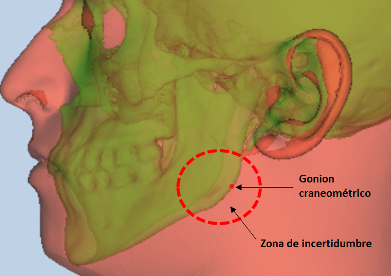 Figure 75. Craniometric gonion and uncertainty area in the soft tissue.
- Avoid marking in subjects with thick facial hair.
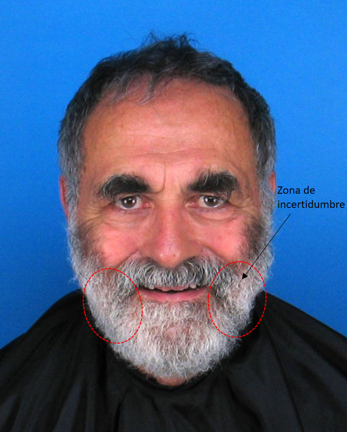 Figure 76. Subject with a thick beard that obscures the view of the facial contour, rendering the location of both gonia unfeasible.
- Avoid marking on obese subjects or subjects with build-up of adipose tissue in the lower region.
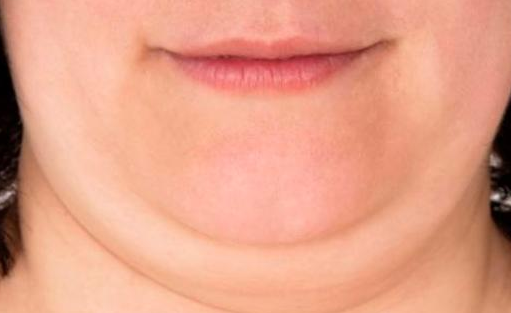 Figure 77. Example of a subject with adipose tissue that obscures the facial contour.
- According to inter and intraobserver studies (Cummaudo et al., 2013; Campomanes-Álvarez et al., 2015), gonion exhibits a high dispersion regardless of the view, due to the fact that it is identified through palpation and has to be estimated on photographs.
Photographic examples:
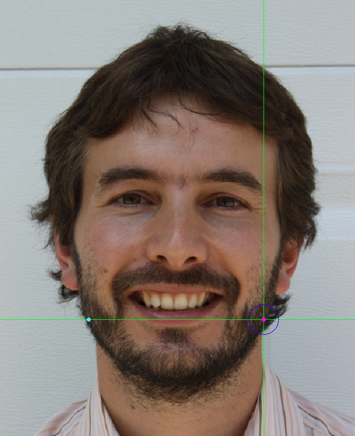

 Figure 78. Gonion marking on a photograph in frontal view (left), lateral view (center) and oblique view (right).